Assembly · alignment · system testing
From separate parts
to a working instrument.
Follow the connection between optics, mechanics, electronics and software as development hardware becomes a complete prototype. Original assembly photographs and design studies show the work between the bench and the enclosed instrument.
PROJECT SPOTLIGHT / LIGHTMED
OCT biometer–topographer
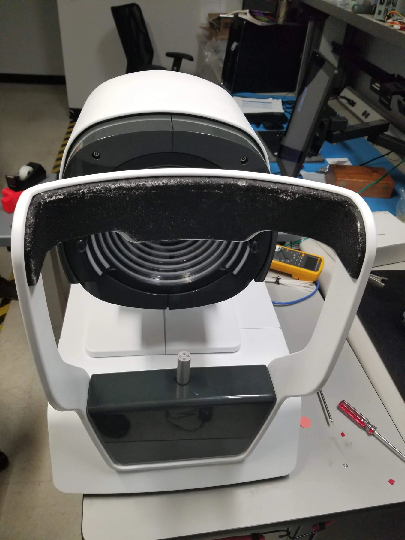
An assembled prototype photographed at LightMed’s facility in San Clemente, California. The development record connects internal architecture and motion-control bench integration with enclosure design and the physical instrument.
The gallery below also follows HERON, CHROMA, VON and WAVELINK through open assemblies, alignment work and system integration. Design studies are identified separately from prototype photographs.
System assembly · optical alignment · bench testing · pilot preparation
15 selected images
LightMed biometer — assembled prototype
The OCT Biometer-Topographer prototype photographed during integration at LightMed’s San Clemente, California facility. The enclosure, ring-target optical head, patient support and base are fitted together on the engineering bench.
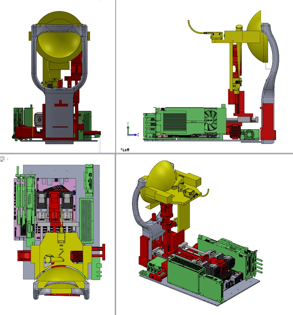
LightMed biometer — internal architecture
An internal component layout from the OCT Biometer-Topographer design review shows the relationship between the optical head, motion system, electronics and display.
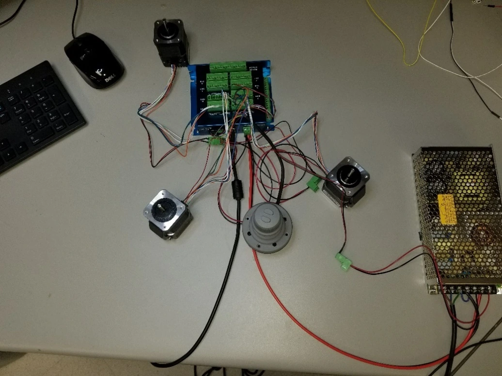
LightMed biometer — motion-control integration
Motor controller, power supply, motors and wiring are connected on the optical-laboratory bench during the LightMed OCT Biometer-Topographer development program.
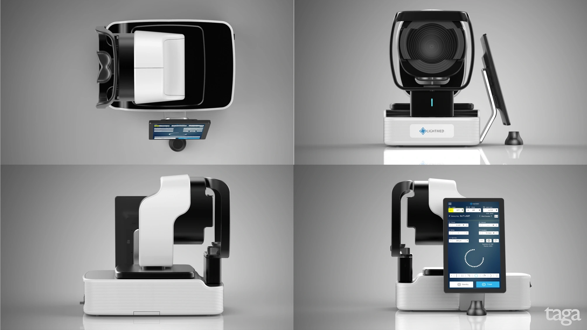
LightMed biometer — enclosure design direction
The industrial-design direction selected during the LightMed OCT Biometer-Topographer review connects the enclosure, patient interface and display arrangement. This image is a design concept.
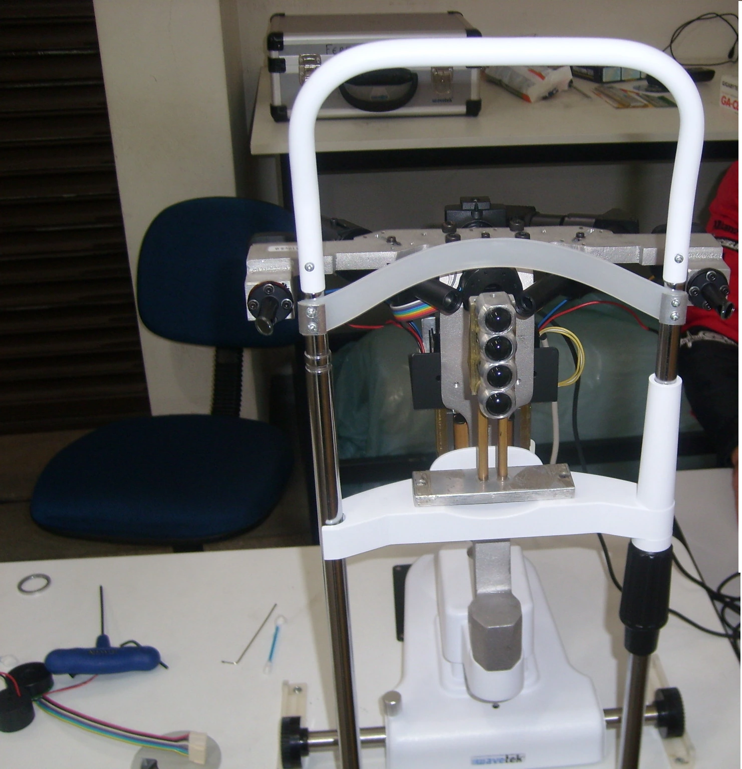
HERON — optical alignment during assembly
A development photograph documents the optical-head assembly and alignment work before the instrument is enclosed.
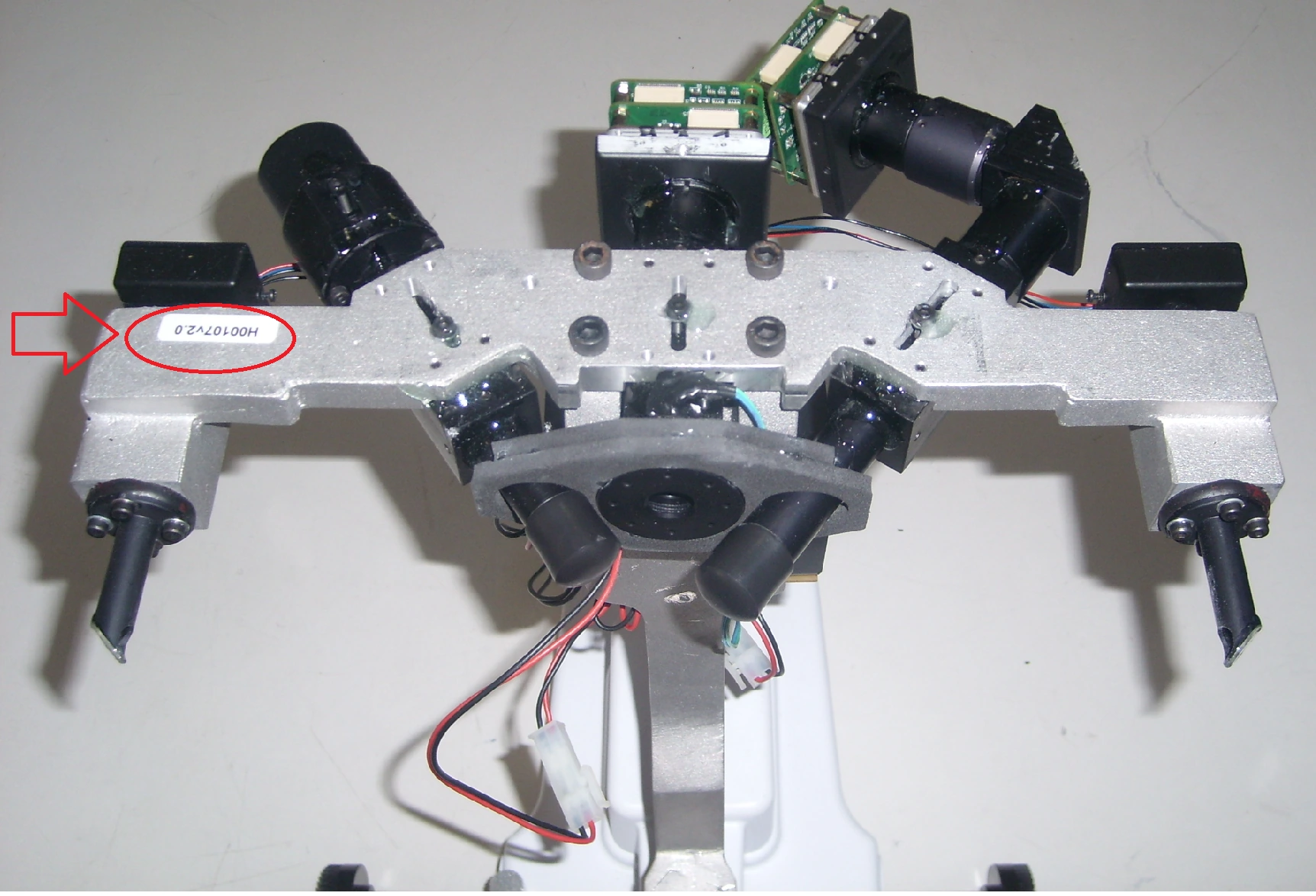
HERON — camera-head integration
Camera-head electronics, cables and optical components are assembled together before the protective housing is fitted.
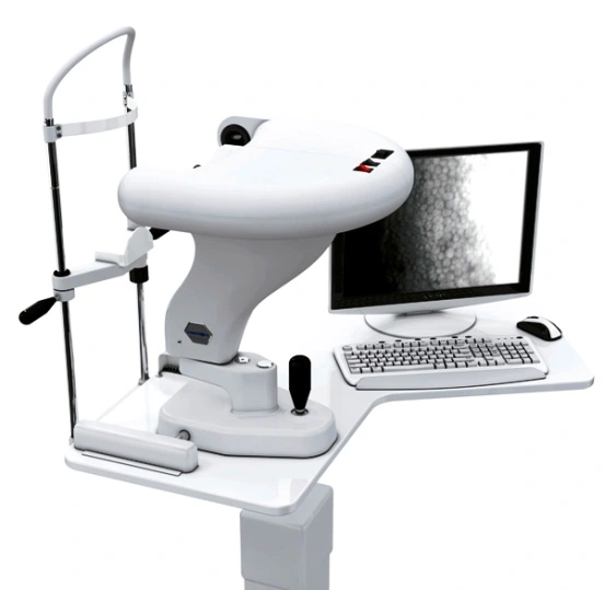
HERON — integrated acquisition workstation
The assembled specular microscope and acquisition workstation connect the optical instrument to its operating software.
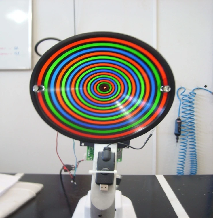
CHROMA — integrating the optical head
The chromatic ring cone and internal components are visible while the corneal-topography prototype is assembled.
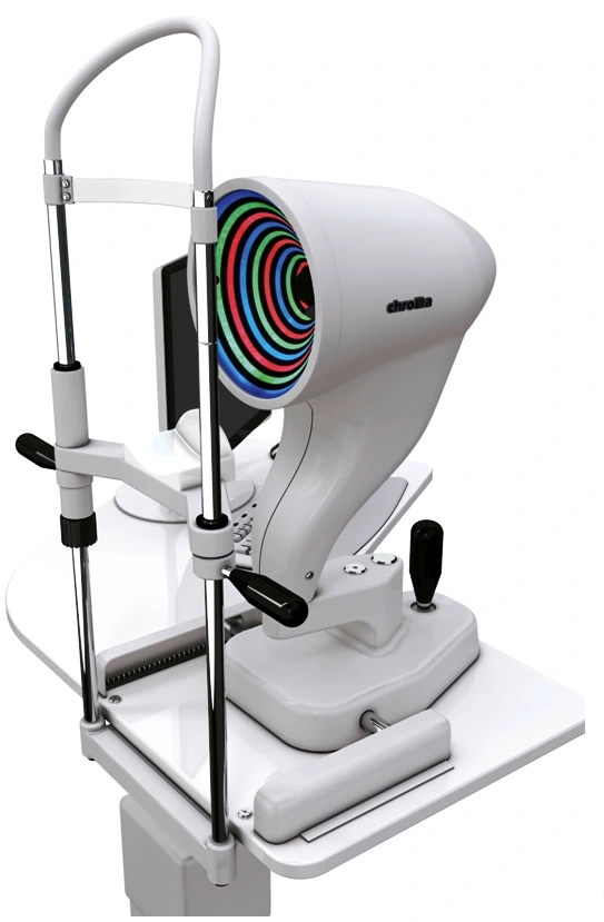
CHROMA — enclosed instrument
The enclosed instrument shows how the optical head, positioning structure, patient interface and base come together.
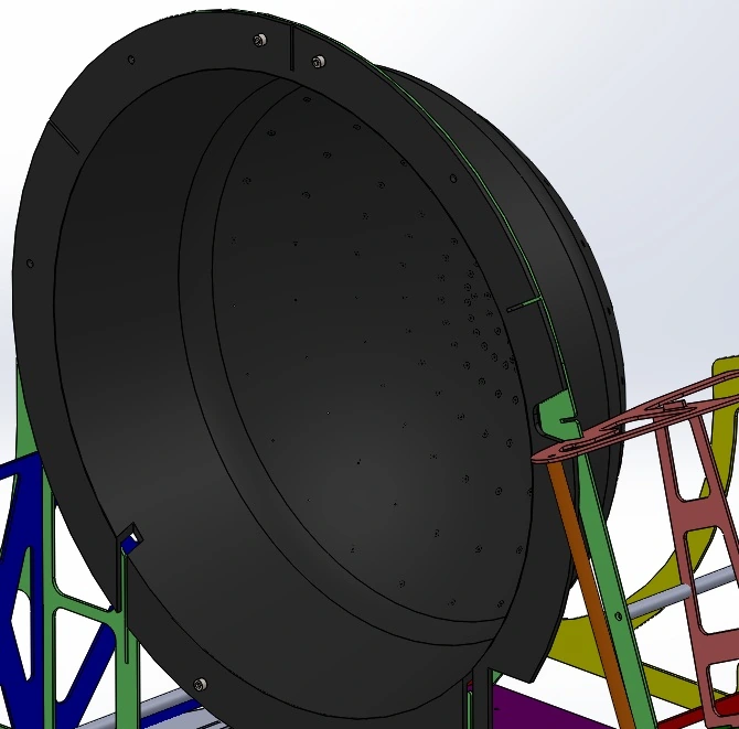
VON — system assembly study
The CAD assembly defines the relationship between the perimeter bowl, structural frame and instrument supports.
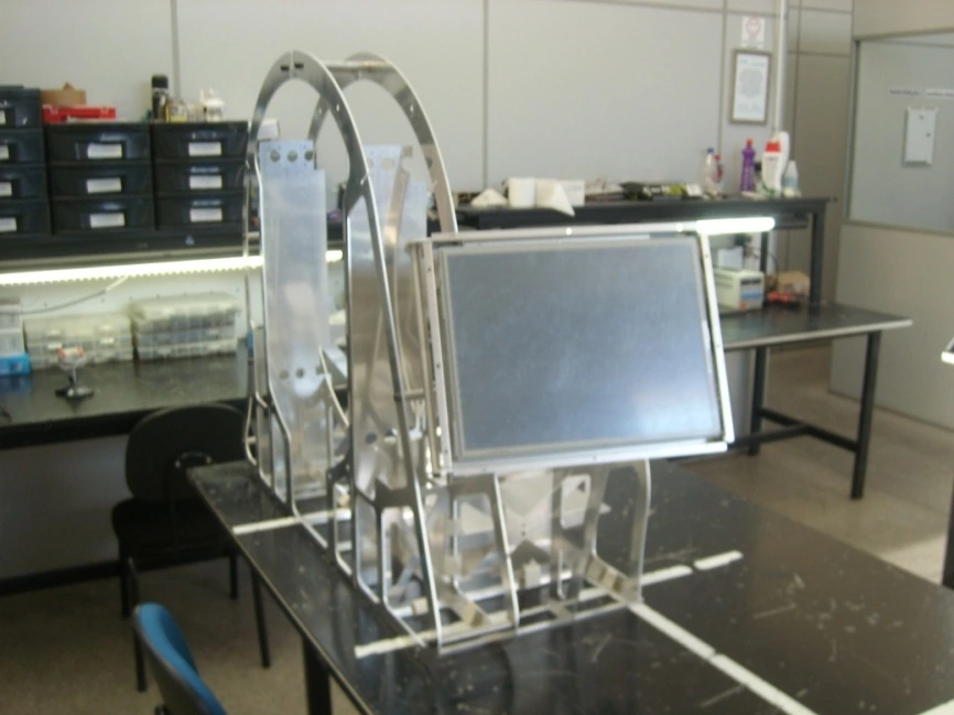
VON — frame and display integration
The physical structural frame carries the display and mounting hardware during instrument assembly.
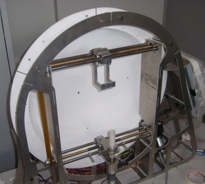
VON — bowl and wiring integration
The perimeter bowl is installed with its wiring and supports, bringing the stimulus assembly into the physical structure.
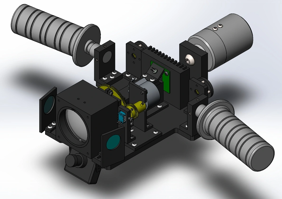
WAVELINK — optical-head assembly design
The optical-head assembly study brings the optics, mounts and surrounding mechanical structure into one design.
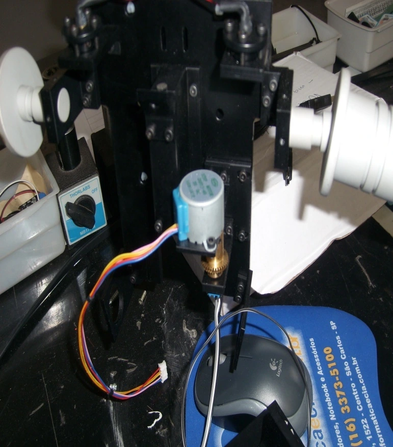
WAVELINK — head integration
The assembled head contains its electronics, optical mounts and wiring before final system integration.
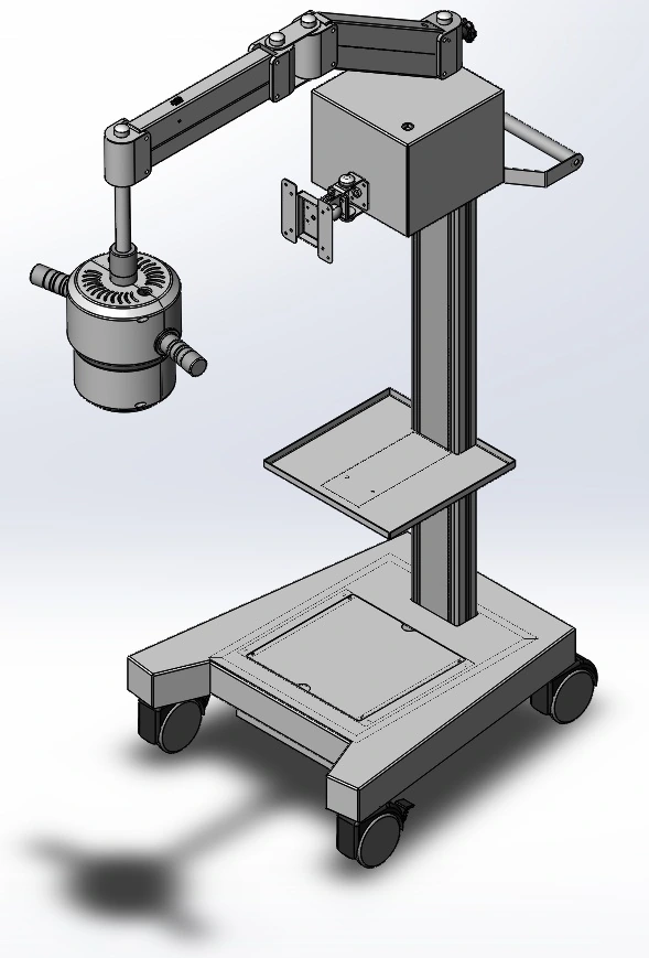
WAVELINK — complete system assembly
The optical head, support arm and wheeled base are assembled into the complete system configuration.