INSIDE DEVELOPMENT
Four disciplines.
One integrated instrument.
A curated look inside the team’s development work: original design studies, native CAD renderings, prototype assemblies, electronics, acquisition software and the integration of complete instruments.
Enclosures · mechanisms · integration
From CAD surfaces
to physical assemblies.
Enclosure and skin design, structural frames, positioning mechanisms and integration details. Explore original CAD models alongside real prototypes at different stages.
Explore mechanics ↗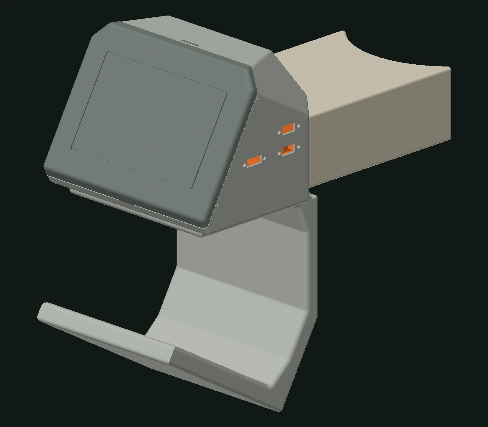
From individual parts to an integrated instrument
The saved Version 2.0 assembly brings together the enclosure, display frame, camera mount, base platform, stand, power-board mount and linear stage. Rendered from the original assembly without rebuilding or changing component geometry.
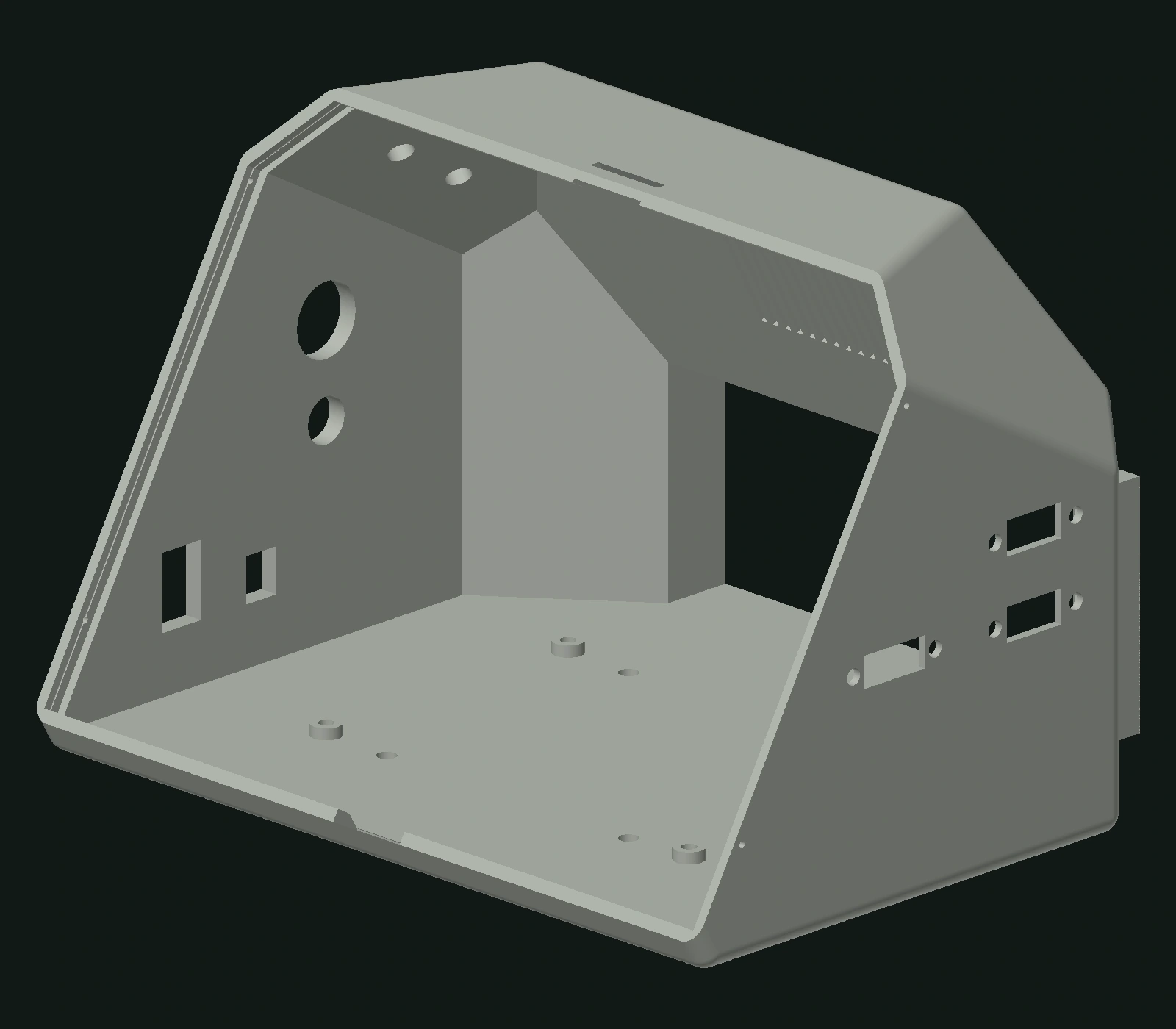
Enclosure designed around the instrument
Original FreeCAD enclosure geometry showing internal mounting bosses, ventilation and connector openings. A practical example of bringing packaging, assembly access and electronics integration into one mechanical design.
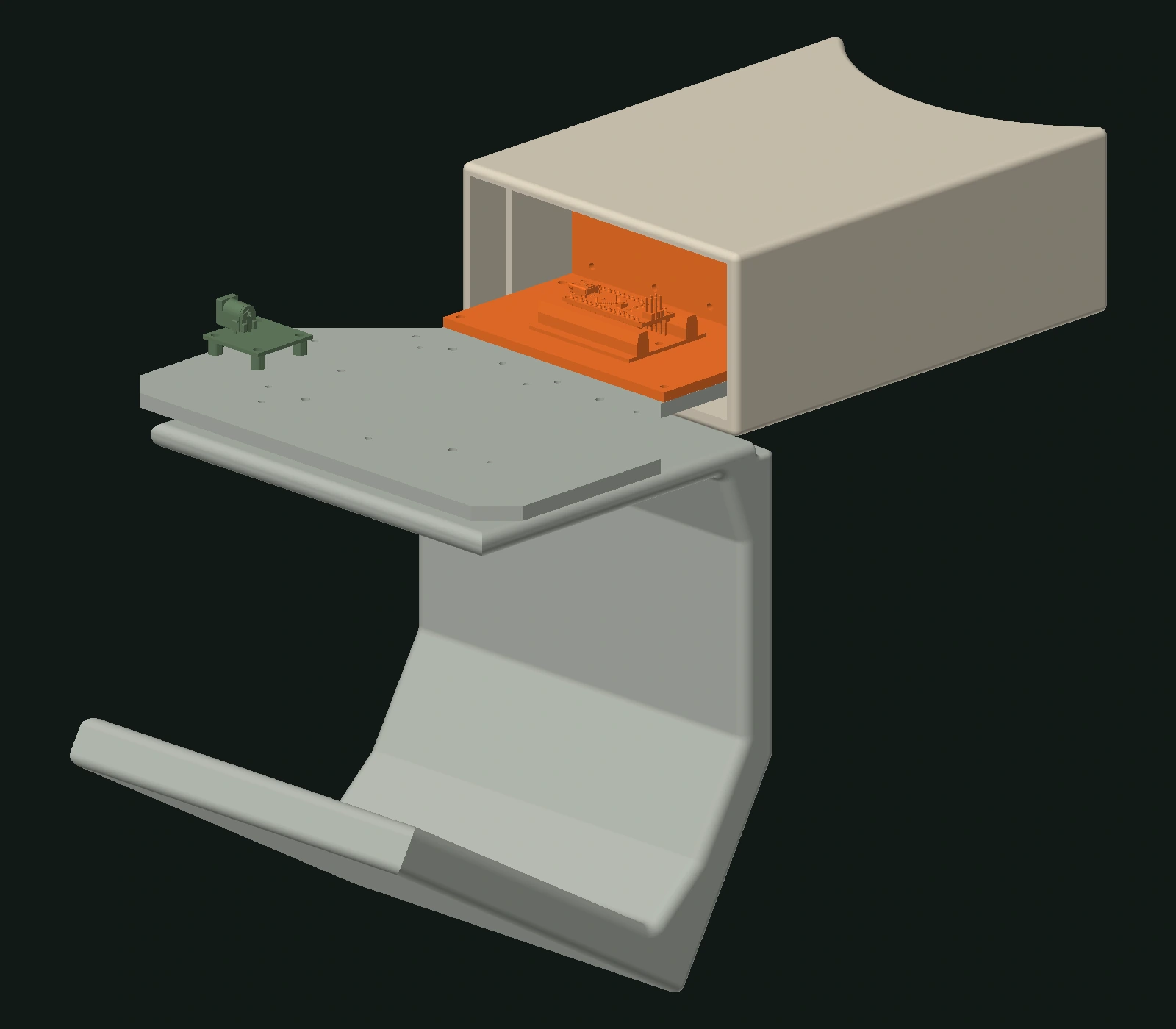
Integration beneath the enclosure
The same saved assembly with only the enclosure skin and display assembly hidden to reveal the camera mounting and electronics integration. Component positions and geometry are unchanged.
Boards · wiring · control
The hardware behind
the instrument.
Populated boards, connectors, wiring harnesses and the integration of sensing and control electronics inside working prototypes.
Explore electronics ↗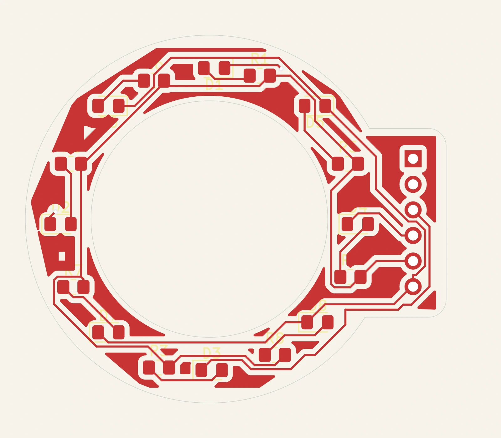
LED illumination PCB — native KiCad layout
A project-specific LED illumination PCB for a specular microscope. The native layout shows circular board geometry, LED footprints, routing and the connector interface.
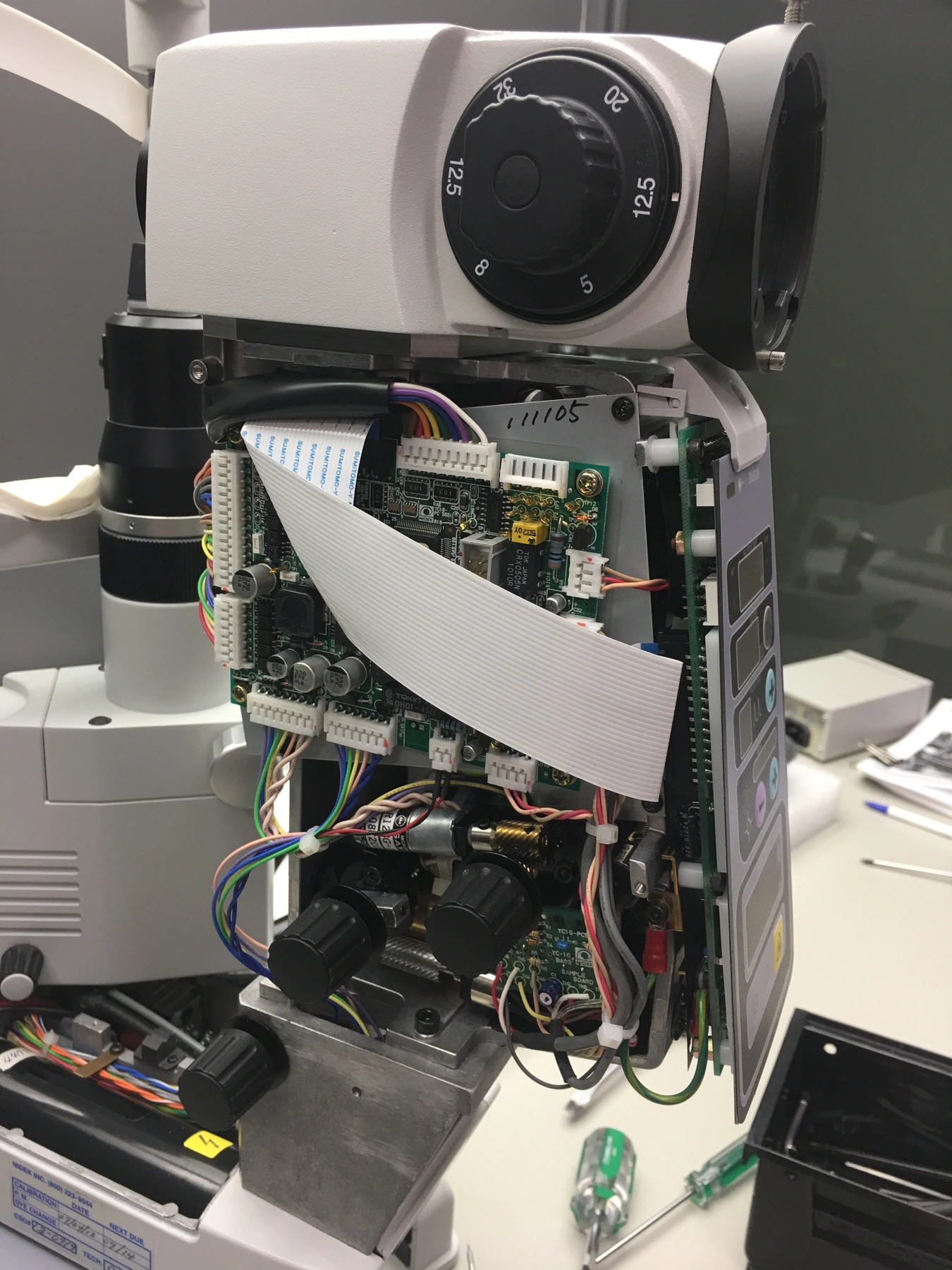
Electronics integration on an optical platform
The exposed optical platform shows connectors, ribbon cable and wiring integrated with commercial electronic and optical modules.
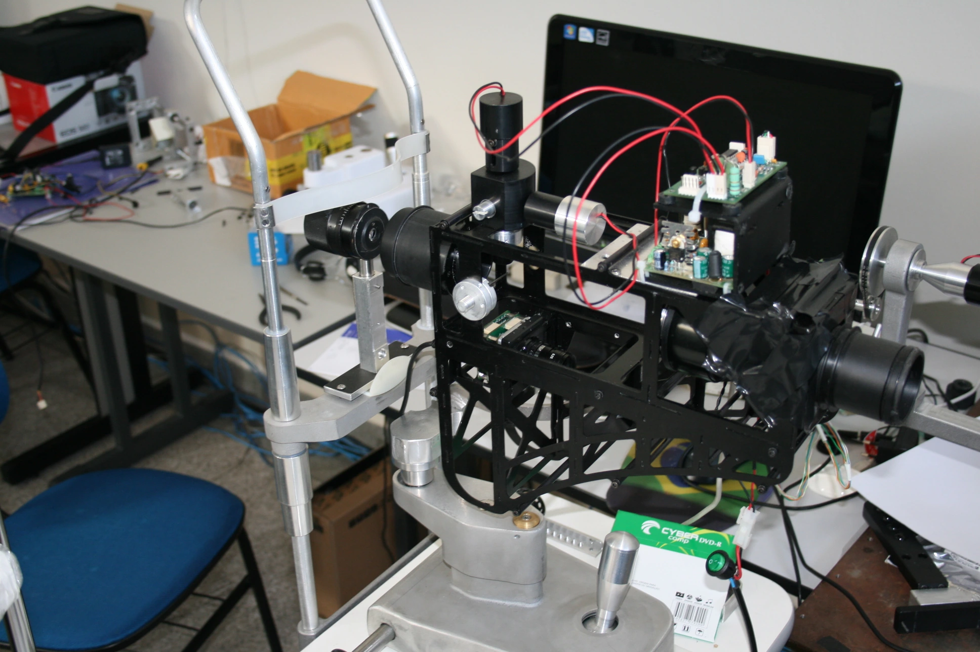
Open CHROMA prototype with optical head, wiring and circuit boards
An open chromatic topographer shows board placement and cable routing alongside the optical head and motion structure.
Lens systems · ray paths · alignment
Where the optical model
meets the bench.
Optical layouts, lens assemblies, illumination arrangements and alignment setups connect modeling decisions with physical instrument development.
Explore optics ↗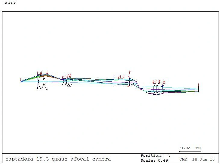
Optical ray-layout study for the HOLTZ image-acquisition path
The original optical layout traces the acquisition path through the imaging elements and folded geometry. This is an archived design diagram, not a new simulation.
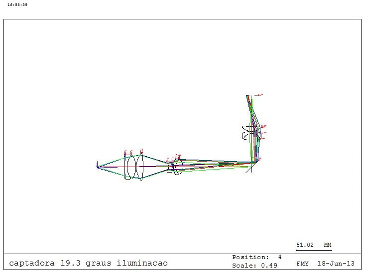
Folded optical illumination layout for HOLTZ
A complementary optical layout study documents the folded illumination arrangement and its relationship to the imaging path.
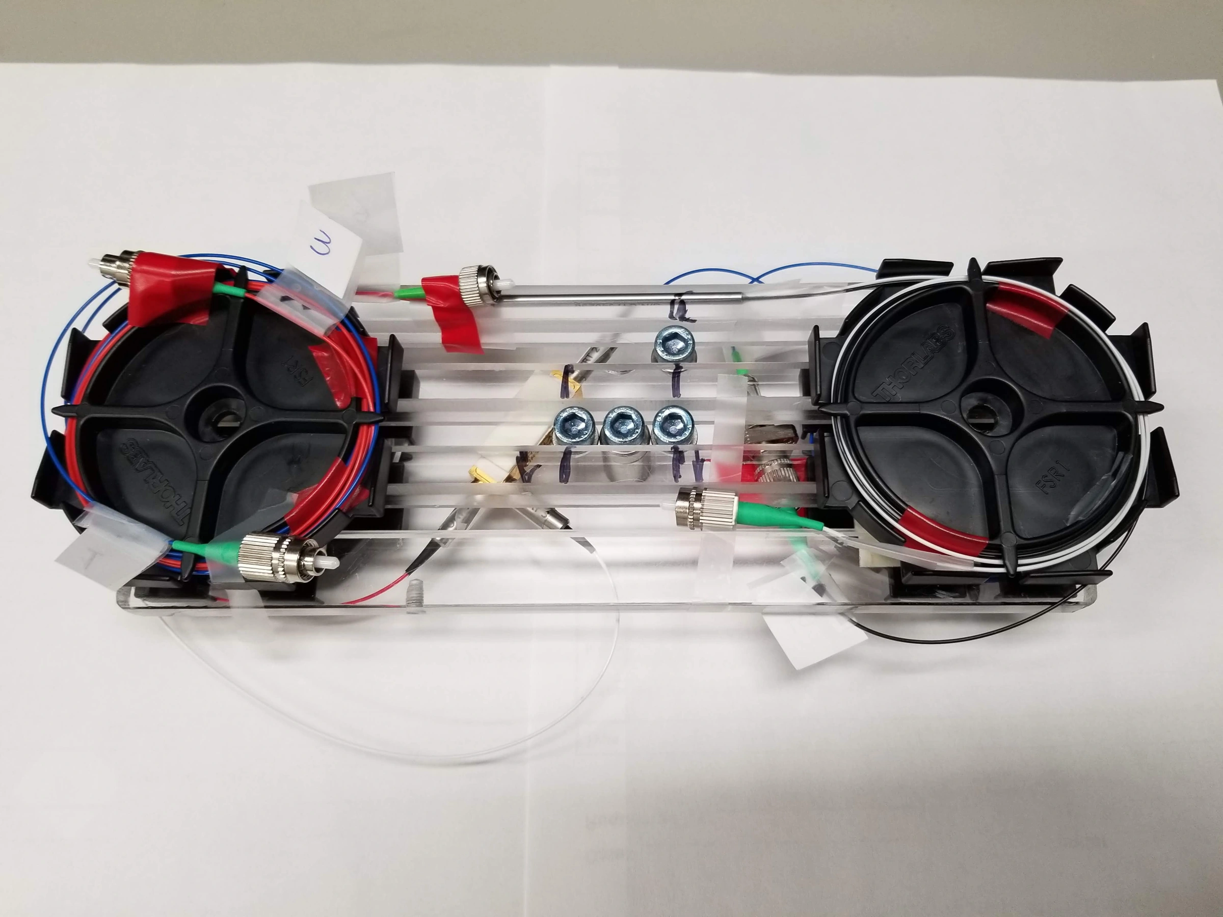
Fiber-optic bench assembly
Optical mounts, fiber components and positioning hardware are brought together on a development bench for alignment and integration.
Acquisition · processing · interfaces
From acquired images
to useful information.
Original acquisition interfaces, stereo-image workflows and reconstruction views show how instrument control and image processing come together.
Explore software ↗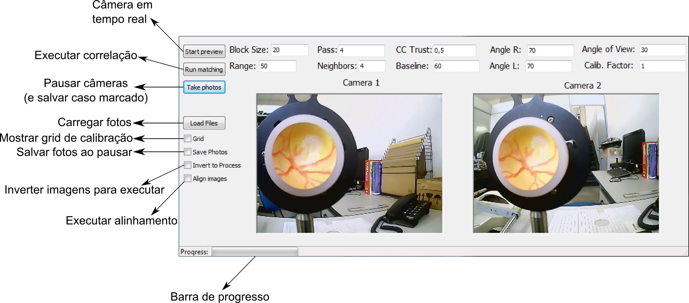
Stereo acquisition interface with function controls
The original stereo-acquisition development interface displays model-eye images alongside acquisition and processing controls.
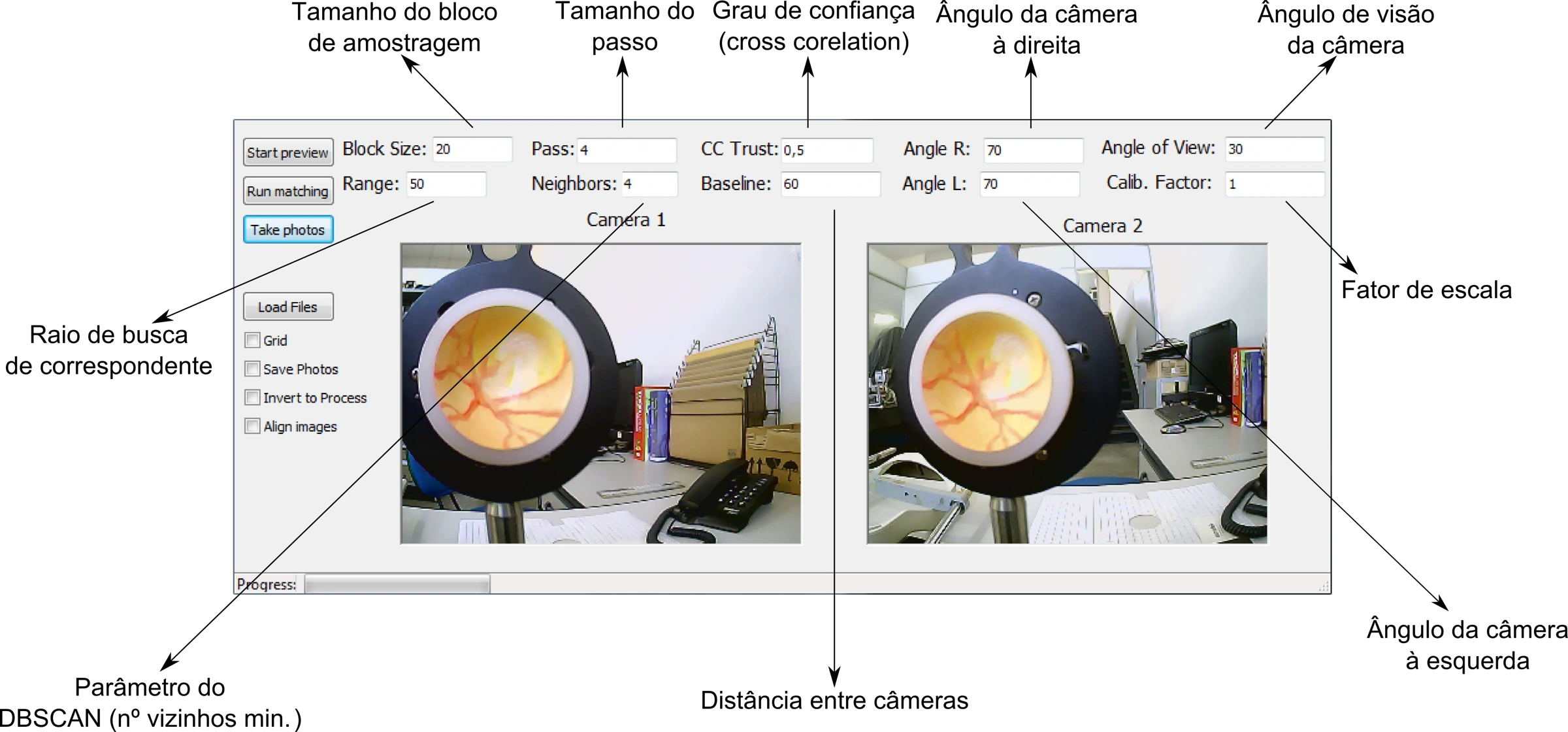
Stereo acquisition development interface with parameter controls
A second development view shows the parameter controls used around the stereo acquisition workflow.
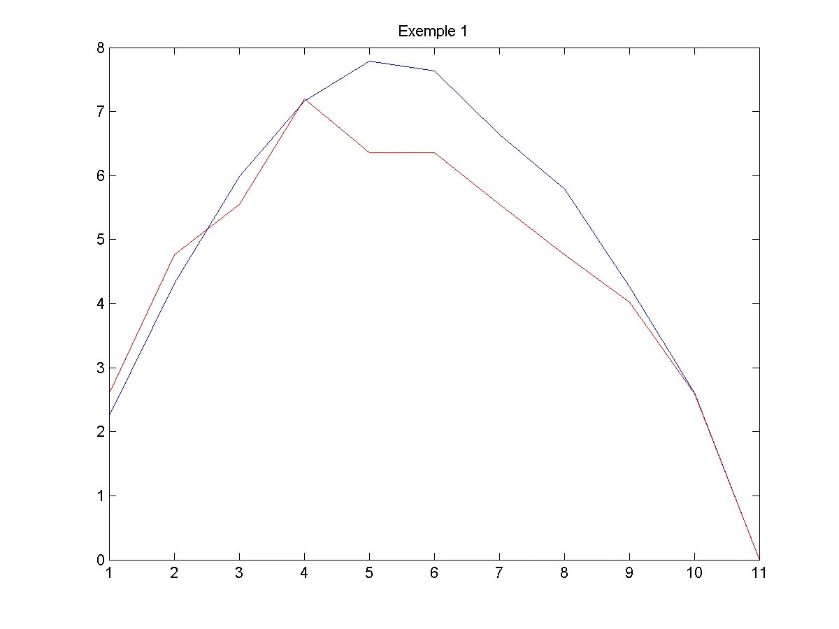
Reference and reconstructed profile comparison from a model-eye analysis
Reference and reconstructed profiles are compared in a model-eye analysis view.
Assembly · alignment · system testing
From separate parts
to a working instrument.
Follow the connection between optics, mechanics, electronics and software as development hardware becomes a complete prototype. Original assembly photographs and design studies show the work between the bench and the enclosed instrument.
Explore integration ↗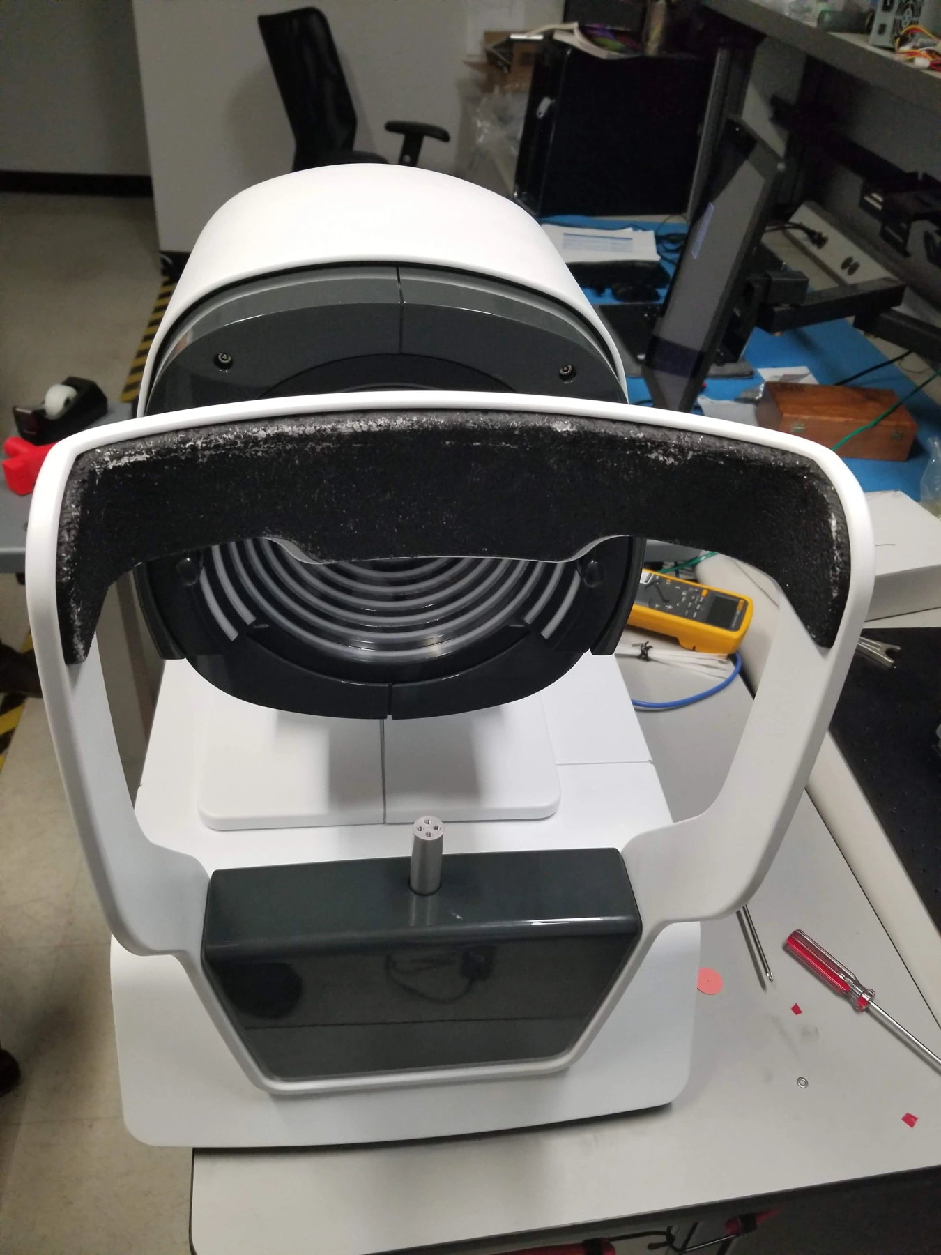
LightMed biometer — assembled prototype
The OCT Biometer-Topographer prototype photographed during integration at LightMed’s San Clemente, California facility. The enclosure, ring-target optical head, patient support and base are fitted together on the engineering bench.
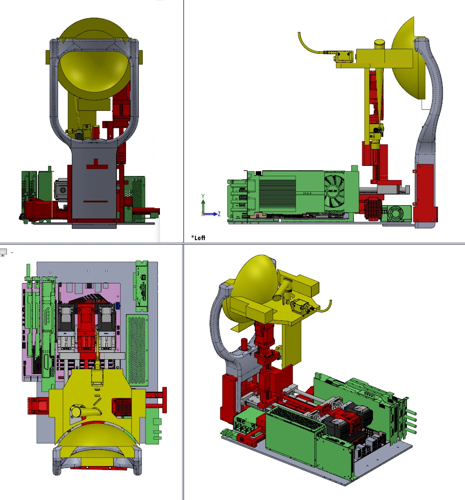
LightMed biometer — internal architecture
An internal component layout from the OCT Biometer-Topographer design review shows the relationship between the optical head, motion system, electronics and display.
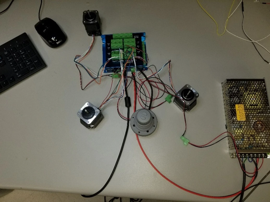
LightMed biometer — motion-control integration
Motor controller, power supply, motors and wiring are connected on the optical-laboratory bench during the LightMed OCT Biometer-Topographer development program.
THE DEVELOPMENT JOURNEY
The decisions between
the sketch and the instrument.
Define & model
Optical layouts, CAD assemblies, electronic architecture and software workflows establish a coherent starting point.
Build & integrate
Prototype housings, boards, wiring and optical stages bring the separate disciplines together.
Measure & refine
Acquisition software and bench setups help the team examine performance and make the next engineering decision.